Correcting a plastic part design using reverse engineering in the mold tool is a sophisticated process that involves several steps and techniques. This approach is often employed when an existing part does not meet quality or performance standards, or when the original design documentation is unavailable. The goal is to enhance the part’s design, improve its manufacturability, or adapt it to new requirements by making modifications directly to the mold tool or through a redesign process informed by the analysis of the current part.
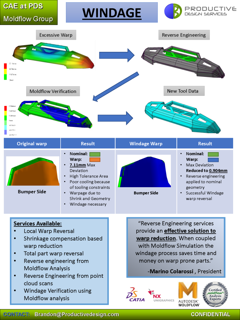
By using Moldflow Software, Steps 1-4 can be completed in the digital stages of part design and production. This eliminates the need to cut and scan the mold first Saving time and money while giving the best part the first time.
PDS is an Expert at Moldflow Based Windage Application.
Here’s how the process generally unfolds:
1. Initial Assessment and 3D Scanning:
The process starts with a thorough assessment of the existing plastic part. This involves identifying the shortcomings, failures, or areas for improvement. The part is then digitized using 3D scanning technology, creating a detailed digital model. This model captures all external geometries and dimensions accurately, serving as a baseline for analysis.
2. Analysis and Identification of Issues:
Using the digital model, engineers perform an analysis to identify the root causes of any defects, inefficiencies, or design limitations. This might involve simulations (such as finite element analysis (FEA) or computational fluid dynamics (CFD)) to understand stress distribution, thermal behavior, or fluid dynamics affecting the part. This step is crucial for pinpointing specific areas within the mold or part design that require modification.
3. Reverse Engineering the Mold Tool:
Once the necessary corrections are identified, the focus shifts to reverse engineering the mold tool itself. This could involve:
- Mold Scanning: If modifications are required directly on the mold, it may also be scanned to create a precise digital representation.
- Design Modifications: Based on the findings, the digital model of the part (and possibly the mold) is modified to correct the identified issues. This can include changes to part geometry, wall thickness, gate locations, cooling channels, or other mold features to improve the quality and performance of the final product.
4. Prototyping and Testing:
Before committing to expensive mold modifications, rapid prototyping techniques (like 3D printing) may be used to produce physical samples of the redesigned part for testing and validation. This step ensures that the proposed changes effectively address the identified issues without introducing new problems.
5. Mold Modification or Fabrication:
Once the design changes are validated, the mold tool is modified or a new mold is fabricated to reflect the revised design. This might involve precise machining, welding, or even the addition of new components to the mold.
6. Production and Final Testing:
With the modified or new mold tool, production can resume. The initial production run is closely monitored, and parts are tested to ensure they meet the desired specifications and quality standards. Adjustments to the molding process (like injection parameters) may also be made to optimize the outcomes.
7. Documentation and Implementation:
The final step involves documenting the changes made during the reverse engineering process and implementing any necessary updates to production protocols, quality control measures, and maintenance routines for the mold tool.
Reverse engineering in mold tool correction is a powerful strategy for improving plastic part designs, particularly when dealing with complex parts, legacy products, or when aiming to enhance performance without starting the design process from scratch. This method leverages advanced technologies and engineering principles to extend the life of molds, reduce costs, and improve product quality.